This was a battery rebuild for my mini electric skateboard build. The original battery would not charge fully even after hours of charging and the output voltage would drop very quickly when disconnected from the charger. This kind of behavior in most cases indicates at cell degradation in one or multiple cells.
The pack was built using Samsung 30Q 18650 Lithium-Ion cells in a 10S3P configuration. Each 30Q cell has a capacity of 3000mAh when fully charged to 4.2V. Maximum current output according to the data sheet is 15 A, but this particular cell can supply even up to 20A consistently according to many tests available. With 10 cells in series (10S) the nominal output voltage is 36V and maximum (fully charged) 42V. Each group (3S) can hold 9000mAh. The total battery capacity is 36V * 9Ah = 324 Wh and it can supply even up to 60A of current.
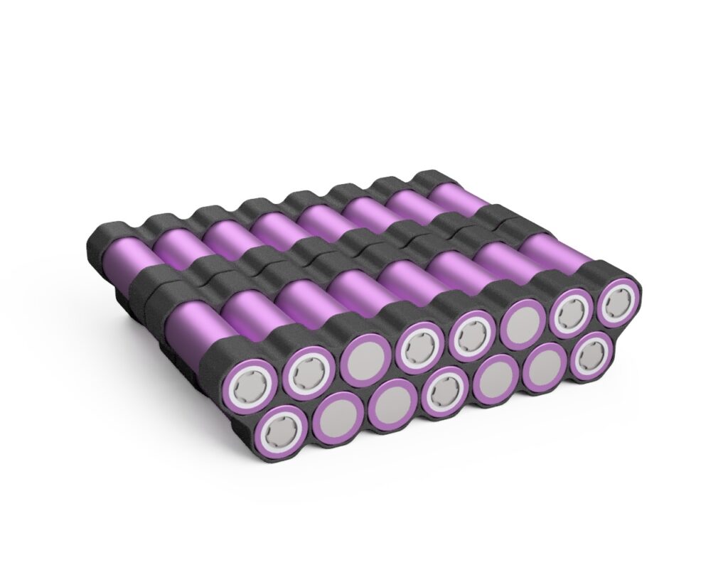
I decided to rebuild the pack completely. Upon disassembly I learned that the original battery pack did not make use of any kind of frame for cells. The cells were being held together with just hot glue and tape, literally. As I’m not a fan of this approach, mainly for safety reasons – I decided to rebuild it slightly differently. It would make the battery slightly larger but it was the correct approach. I decided to design and 3D print a frame for the cells. The frame would ensure proper distance between cells, increase the cell rigidity and allow for easier cell replacement should it become necessary. I experimented with few frame designs. The first ones were using round cell holes. Unfortunately trying to insert a round cell into a round hole that the cell cannot easily slide out but isn’t difficult to insert either requires very high manufacturing tolerance of the hole. I decided to change the approach and I switched to an octagonal hole design. This change made the design complaint because the sides of the octagon shape can bend slightly to conform to the diameter of the cell. Manufacturing tolerance was no longer an issue.
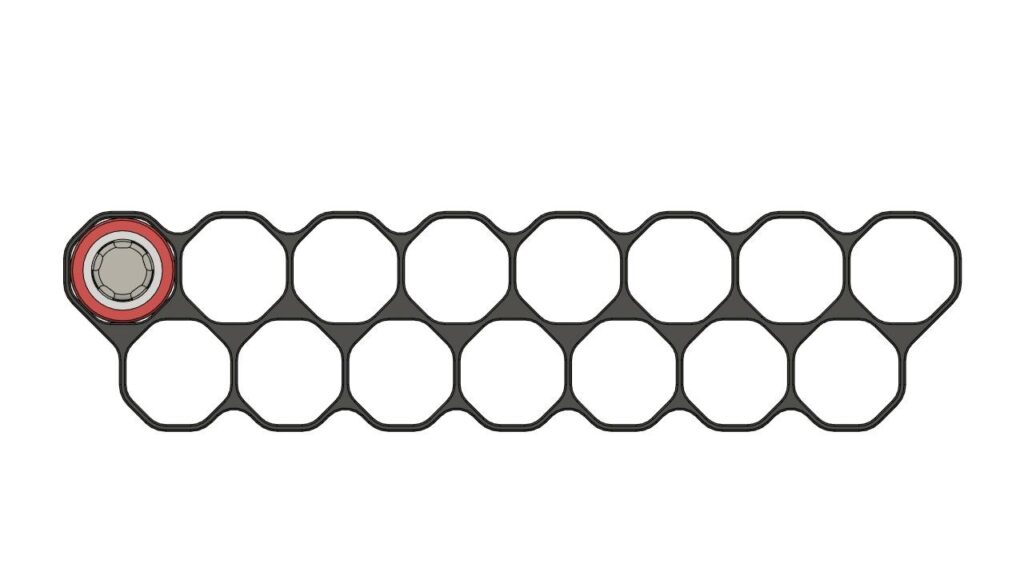
A small amount of hot glue can be used to attach the cells to the frames. The glue only prevents the frames from sliding out. Should an individual cell need replacing however, the hot glue can easily be removed with a drop of isopropyl alcohol and the cell can slide out.

With the frame design completed I acquired some depackaged Samsung 30Q cells and proceeded with the build. The cells are separated in groups of 3, with the cell direction changing every group. I inserted all the cells into the frames and used blue tape to plan out the placement of nickel strips before spot welding everything. In the spirit of “measure twice, cut once” of course 🙂
When I was satisfied that everything looked correctly I added some fishpaper adhesive rings on all positive sides of the cells. These are meant to prevent a short circuit should the heat shrink wrap between the cell and the nickel strip become damaged. I used 8×0.2 mm full nickel strips for welding with at least two strips between each group connection and on the battery terminal ends. Dual strips were necessary as 0.2 mm is the maximum thickness my spot welder can reliably weld. A single strip of that thickness however would not meet the expected power draw requirement.
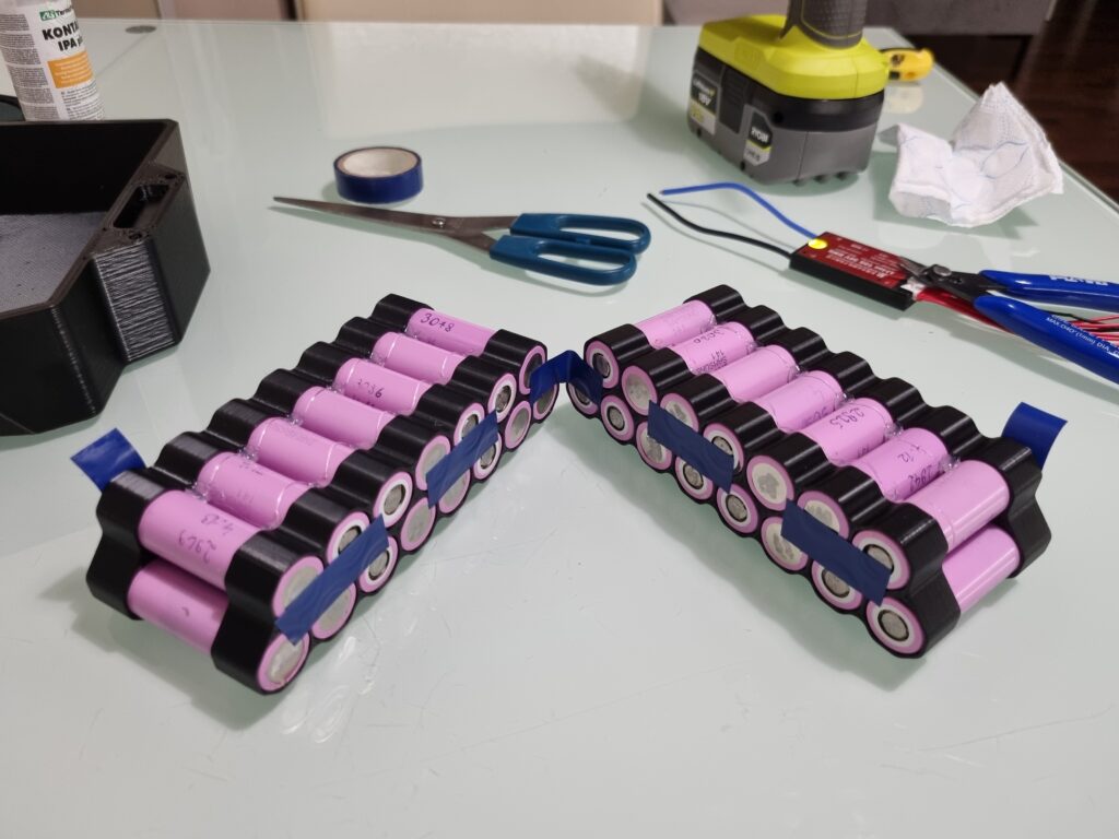
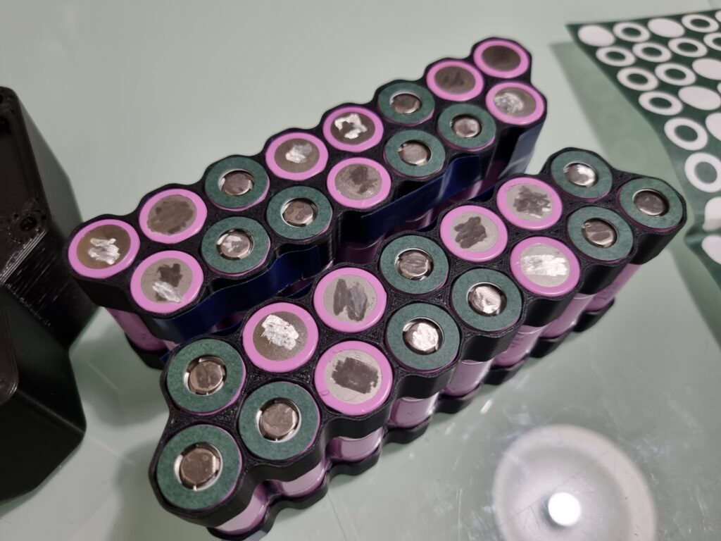
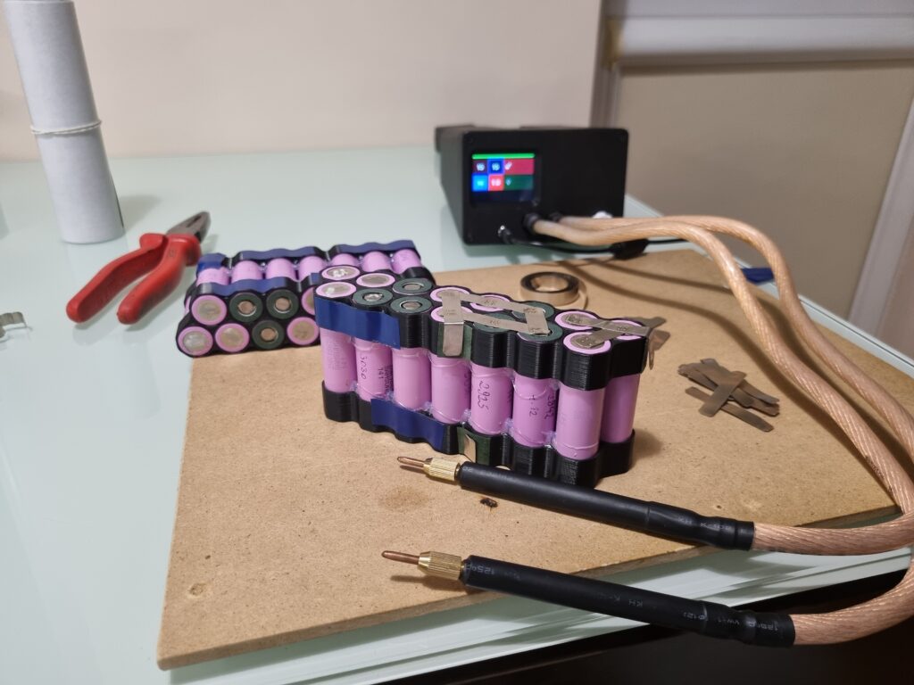
For each group I created a small terminal for balancing. When everything was finished I used two, self-adhesive pieces of fishpaper to electrically isolate both pack sections from each other. Another two pieces of fishpaper were used on the outer sides. After that the pack was bonded together with glass fiber reinforced adhesive tape. This type of tape is used to minimize tape stretching which can be possible with non reinforced tape.
The original battery design used a Battery Management System (BMS) for both charging and discharging. Because I was unsure what caused the battery degradation initially and I couldn’t rule out the BMS as a possible cause I decided to replace it. While looking for a replacement I could not find a BMS with a discharge rating of at least 30 A in a small enough package.
Instead I decided on the next best thing – a BMS discharge bypass. With this approach the battery is still charged and balanced though the BMS, but discharged directly from the pack end terminals. The main drawbacks of this approach is lack of overdischarge and overcurrent protection. Fortunately the first aspect is a is a non issue because an electric skateboard with a dead battery becomes unrideable and the ESC automatically turns itself off after a few minutes. The second issue can be overcome with a fuse. So ultimately I decided on a DALY 10S BMS and a 40A automotive fuse.
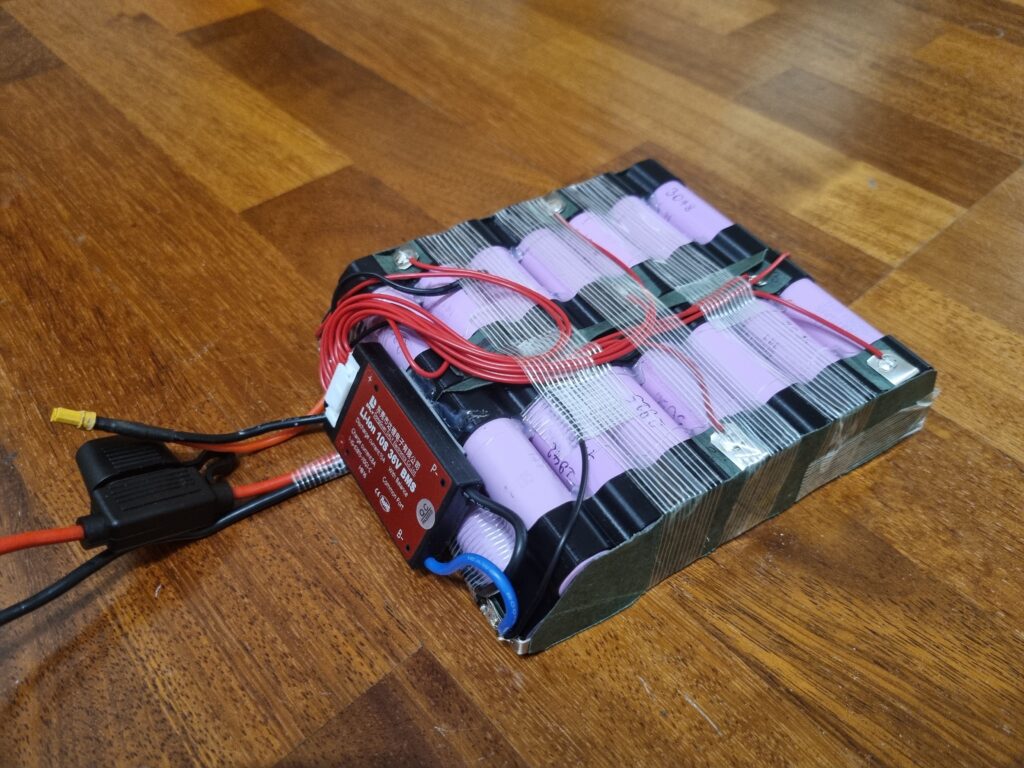
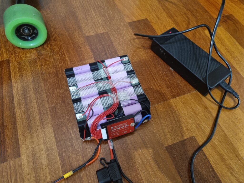
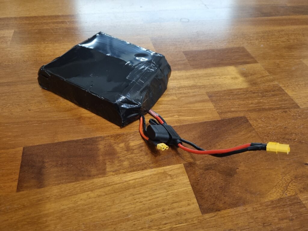
I soldered in the balancing leads and connected performed a charging test. Once I confirmed that everything worked correctly I covered the cells with black shrink wrap and used black tape on exposed ends to protect it from dust and moisture. The battery was done. Thanks for reading 🙂